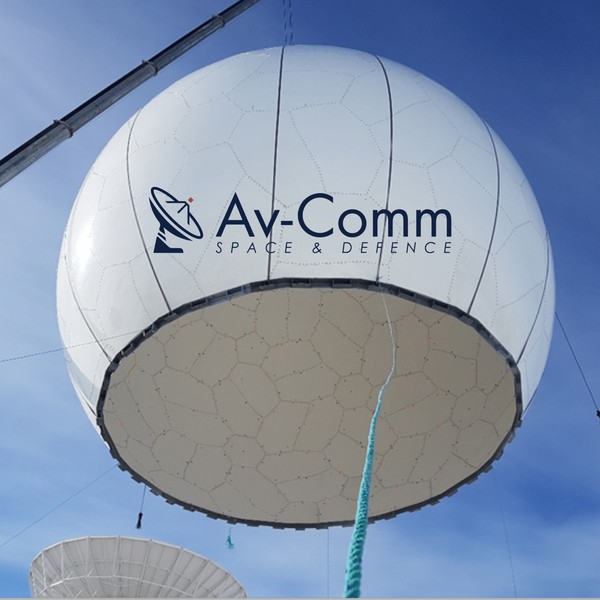
 Ground antennas > 10.5m Composite Sandwich Radomes for Ground Station Antennas
Key highlights
- RF‑engineered sandwich composite panels designed to minimise insertion loss, VSWR impact, and radiation pattern distortion while providing full environmental enclosure.
- Truncated spherical radome geometry optimised for antenna look angles, reducing multipath effects and maintaining consistent beam performance.
- Fully passive design with no active cooling or moving components, eliminating power dependency and reducing system failure points.
- Structural and environmental protection against high wind loads, precipitation, UV exposure, dust ingress, and ice accumulation, improving system availability and maintenance intervals.
- Tunable electromagnetic wall construction supporting operation from UHF through V‑Band (~50 GHz), with material selection matched to frequency band and performance requirements.
- Engineered for site-specific conditions, including compliance with Australian and New Zealand standards for structural, wind loading, and installation.
- Lifecycle optimisation through reduced weather-induced degradation, improved uptime, and predictable maintenance requirements.
Applications
- Satellite communications (SATCOM) ground stations
Provides a controlled RF environment for earth‑station antennas, mitigating wind loading and environmental attenuation while maintaining low-loss transmission. Suitable for commercial teleports, gateway stations, and defence SATCOM infrastructure.
- Telemetry, Tracking & Control (TT&C)
Supports high‑reliability TT&C links by protecting antenna systems from environmental variability that can introduce pointing errors, signal instability, or degradation in link margin.
- Meteorological and weather radar systems
Enables continuous operation of weather radar installations in harsh climates by preventing radome icing, water ingress, and wind-induced structural deformation that could impact radar accuracy.
- Air traffic control and surveillance radar
Used in primary and secondary radar systems where consistent electromagnetic performance and structural stability are required to maintain detection accuracy and operational reliability.
- Phased-array and long-range radar systems
Compatible with advanced radar architectures including phased-array and 3D radar, where broadband RF transparency, structural integrity, and minimal electromagnetic interference are critical.
- Remote and extreme-environment deployments
Optimised for installations in offshore, desert, alpine, or other remote locations, reducing maintenance frequency and improving system availability under severe weather and temperature cycling conditions.
Key features
- RF‑transparent sandwich composite structure
Glass‑reinforced polymer (GRP) skins bonded to a low‑density core provide a high stiffness‑to‑weight ratio while maintaining low dielectric constant and loss tangent. This construction minimises insertion loss, boresight error, and pattern distortion across the operational band.
- Panelised truncated spherical architecture
Doubly curved, modular panels form a truncated spherical enclosure, optimised for structural efficiency and uniform electromagnetic response. Panelised design enables controlled factory fabrication, transport efficiency, and repeatable on‑site assembly.
- Broadband frequency capability (UHF to V‑Band)
Radome wall configurations are tunable for specific frequency bands (L, S, C, X, Ku, Ka, V), with material stack‑ups engineered to balance transmission efficiency, reflection, and phase stability across the required spectrum.
- Passive, zero‑power operation
The radome operates without active thermal regulation or mechanical systems, eliminating power requirements and reducing operational complexity and failure modes, particularly advantageous for remote or unmanned installations.
- Environmental and mechanical protection
Provides a stable operating envelope by shielding antenna systems from wind loading, precipitation, particulates, UV exposure, and thermal cycling, reducing mechanical stress and environmental RF variability.
- High wind and cyclone design capability
Structural design accommodates extreme wind regimes, including cyclone-prone regions, with site‑specific analysis available. Load cases consider wind pressure, gust factors, and structural fatigue in accordance with applicable AU/NZ standards.
- Configurable geometry and integration interfaces
Diameter, truncation height, foundation interface, access systems, and penetrations (RF cabling, power, ventilation) are configurable to match antenna size, mount geometry, and site constraints.
- Frequency‑specific EM optimisation
Laminate schedules, core materials, thickness, and surface coatings can be tailored to minimise insertion loss and phase errors while maintaining structural performance, enabling optimisation for narrowband or broadband mission requirements.
- Improved system availability and lifecycle performance
By isolating the antenna from environmental loading and contamination, the radome reduces maintenance intervals, mitigates weather‑induced performance degradation, and extends overall system service life.
- Standards‑compliant engineering and documentation
Design packages can include structural analysis, wind loading calculations, lightning protection and grounding schemes, and civil interface documentation aligned with Australian and New Zealand engineering standards.
- Compatibility with diverse antenna systems and missions
Suitable for parabolic reflectors, tracking systems, and radar apertures used in SATCOM, TT&C, and surveillance applications where consistent RF performance and environmental resilience are critical.
Customization
- Geometric configuration
Diameter, truncation height, and panel layout tailored to antenna size, mount geometry, and elevation masks (included in standard design scope).
- Frequency‑specific EM tuning
Wall construction (skin, core, thickness) optimised for target bands (L/S/C/X/Ku/Ka/V) to balance insertion loss and phase stability (standard within typical ranges; advanced or multi‑band tuning may incur additional cost).
- Surface treatments
Optional hydrophobic, anti‑static, UV‑resistant coatings and colour matching for site or regulatory requirements (additional cost).
- Access and integration
RF‑sealed doors, hatches, and custom cable/vent penetrations designed to maintain EM integrity (standard; complex configurations may vary).
- Foundations and grounding
Anchor ring design, lightning protection, and earthing/bonding interfaces engineered to site requirements (site‑specific work may be costed separately).
Flight heritage
This is a ground‑based radome and does not have in‑orbit flight heritage. Instead, performance heritage is defined by proven field deployment of composite sandwich radome structures across global SATCOM, TT&C, and radar installations.
Composite GRP sandwich construction is a mature, industry‑standard solution, with well‑characterised electromagnetic and structural behaviour validated through long‑term operational use in harsh environments.
The 10.5 m radome design leverages established materials, laminate architectures, and panelised construction methods consistent with widely deployed ground‑station radomes. Operational performance is demonstrated through sustained structural integrity, environmental protection, and stable RF characteristics over extended service lifecycles, in accordance with applicable engineering standards.
Manufacturing
The 10.5 m composite sandwich radome is manufactured using established GRP sandwich construction techniques widely adopted in large‑aperture ground radomes. Each panel comprises multi‑layer glass‑reinforced polymer (GRP) skins bonded to a closed‑cell, low‑dielectric foam core, providing a high stiffness‑to‑weight ratio with controlled dielectric properties.
Panels are fabricated as doubly‑curved segments using controlled moulding processes to achieve consistent geometry and uniform laminate thickness. This is critical for maintaining predictable electromagnetic performance, including low insertion loss, minimal phase error, and reduced pattern distortion across the radome surface.
The radome utilises a panelised architecture, where precision‑manufactured segments are mechanically fastened and sealed to form a truncated spherical structure. This approach supports transport efficiency, repeatable field assembly, and reliable long‑term structural performance under environmental loading.
Manufacturing controls include specified laminate lay‑ups, core machining tolerances, and controlled curing conditions to ensure repeatable mechanical and dielectric characteristics. Panel‑to‑panel tolerances and joint interfaces are designed to minimise RF discontinuities and maintain overall enclosure integrity.
Material selection and wall construction can be tuned during manufacture to meet frequency‑specific requirements from UHF to V‑Band, with optimisation of thickness, dielectric constant, and loss tangent to meet defined RF performance targets.
Quality assurance processes include dimensional verification, laminate inspection, and assembly fit‑up checks. Structural and RF performance criteria are validated against project specifications and applicable engineering standards. Optional surface coatings (e.g. hydrophobic, UV‑resistant) are applied during finishing to enhance environmental durability and reduce long‑term maintenance requirements.
Testing & qualification
Qualified as a ground‑based, RF‑transparent composite radome for SATCOM/radar use, consistent with established sandwich‑panel radome constructions used globally.
Environmental protection scope covers wind, rain, sand, snow/ice, UV exposure, and temperature cycling, aligning with the role and capabilities of earth‑station radomes.
Structural & environmental qualification (type tests & analyses)
Wind loading: Structural design and verification performed via finite element analysis (FEA) and panel‑level coupon testing; radomes of this class are commonly engineered for severe wind regimes (including cyclone regions) with certification delivered per project requirements.
Panelised assembly verification: Doubly‑curved, polygonal panels are bolted and sealed; qualification includes joint fastener strength, flange stiffness, and watertightness checks typical of truncated spherical, panelised architectures.
Ingress protection & weather‑tightness: Seal integrity and panel fit are inspected and tested to ensure resistance to driven rain, dust, snow/ice, and thermal expansion effects that could impact RF or structural performance.
Lightning protection & grounding: Earthing/bonding and lightning details are provided as part of the structural/mechanical design package in line with industry practice for composite radomes.
Electromagnetic (EM) qualification
Transmission loss & pattern distortion: Wall builds (skins/core thickness/resin system) are tuned for target bands (e.g., L/S/C/X/Ku/Ka/V). Qualification includes transmission loss, boresight error, and sidelobe impact across operating look‑angles, consistent with dielectric radome methods for UHF–V‑Band applications.
Panel‑to‑panel uniformity: Manufacturing controls maintain uniform thickness and dielectric properties to minimise EM discontinuities at seams, a recognised requirement for composite radomes.
Materials & process qualification
Composite sandwich construction: Multi‑layer fiberglass skins with foam‑core panels are qualified via laminate coupon testing (tensile/compressive/flexural), core shear, skin‑core bond, and moisture/temperature exposure, reflecting standard practice for ground‑based composite radomes.
Panel fabrication: Controlled lay‑up, cure, and post‑cure processes are applied to achieve consistent mechanical and dielectric performance; dimensional and fit inspections verify panel geometry before shipment/assembly.
Factory & site acceptance
Factory Acceptance Tests (FAT): Panel dimensional checks, laminate property verification, hardware conformity, and coating adhesion; documentation package includes drawings, materials certs, and QC records—practices reflected in industry radome programs.
Site Acceptance Tests (SAT): On‑site assembly inspection, seam/fastener torque verification, sealant continuity, drainage checks, and post‑assembly EM baseline measurements (as applicable) to confirm performance after installation.
Testing capabilities referenced by industry
Comprehensive radome suppliers document RF testing, non‑destructive testing (NDT), structural tests, and environmental qualification (e.g., shock, vibration, fatigue, lightning), illustrating the test regimes commonly applied to composite radomes and supporting infrastructure. Your project leverages comparable methods appropriate to a ground‑based enclosure.
Project‑specific certification
Final certification packages include structural/wind calculations, foundation design, earthing/lightning details, and compliance statements to local codes and customer specifications to ensure safe, reliable, and long‑term operation at the installation site.
Export control
This product is a ground‑based composite radome and is not inherently listed under a specific Export Control Classification Number (ECCN). Most commercial, non‑military radomes fall under EAR99, meaning they are subject to the U.S. Export Administration Regulations (EAR) but typically do not require a license unless exported to restricted destinations, prohibited end‑users, or for prohibited end‑uses. Exporters are responsible for ensuring compliance with the EAR, including screening counterparties and determining whether a license is required based on destination and end‑use.
If the radome is incorporated into, modified for, or delivered in support of military radar or SATCOM systems, it may require classification under the Commerce Control List (CCL) or review for potential ITAR applicability. When needed, customers can request a formal BIS commodity classification (CCATS) to confirm export status.
Distributors
This product is supplied directly by Av‑Comm Space & Defence to customers in Australia, New Zealand, and international markets. At present, Av‑Comm does not utilise third‑party national or regional distributors for composite sandwich radomes; all sales, engineering support, certification, and after‑sales services are handled in‑house to ensure quality, configuration accuracy, and compliance.
If required for specific projects, Av‑Comm can coordinate with approved local installation partners, civil engineers, or logistics providers; however, these partners do not act as product distributors.
Customers
Av‑Comm’s radome and ground‑station capabilities have been contracted and utilised by several recognised organisations across meteorology, satellite communications, and defence‑adjacent programs. Publicly documented customers include:
Australian Bureau of Meteorology (BOM) — Engaged Av‑Comm to relocate, refurbish, and reinstall a 4.2 m radome and antenna system at its Middle Point facility, demonstrating Av‑Comm’s specialist capability in radome handling and ground‑station sustainment.
Intellian - Public testimonial praising Av‑Comm’s antenna installation and support services, indicating collaboration on satellite ground‑station infrastructure.
Lockheed Martin Australia & New Zealand - Publicly acknowledges Av‑Comm as a capable supplier supporting satellite communications programs including SouthPAN and Defence SATCOM projects.
Telikom PNG - Multiple public statements highlight Av‑Comm’s work improving critical national communications infrastructure, including antenna and radome‑related site upgrades.
Disclaimer: satsearch is not responsible for any mistakes on this page, although we do our best to ensure correctness. Please report any mistakes to us.
Last updated: 2026-05-26

10.5m Composite Sandwich Radomes for Ground Station Antennas
Export