 Satellites and subsystems > Attitude > Attitude sensors > Earth sensors and horizon sensors > Earth Sensors / Horizon Scanners for Micro-Satellites
Key highlights
The earth sensor is composed of four thermopile-optical assemblies viewing four fields of view through a single 13.5mm cut-on optical filter/window, as is shown in Figure 1. Each earth sensor measures the attitude of the spacecraft relative to its axis. For Pitch and Roll attitude readout, two sensors mounted 90° apart around the spacecraft’s yaw axis are required, as is shown in Figure 1. Each sensor is mounted such that the lower edges of its fields protrude 10° below the nominal earth horizon at the orbit altitude. The output of each field is a D.C. voltage proportional to the earth radiance multiplied by the solid angle subtended by the earth in that detector’s field. Two additional detectors are used to correct for earth radiance variation as a function of season and position in the orbit. One of these fields views cold space continually, while the other is always below the earth horizon and thereby measures the earth radiance in the vicinity of the spacecraft’s position in the orbit.
These four D.C. analog signals for each sensor measured relative to ground are amplified and routed to a multiplexer and A/D converter, which subsystems are normally part of the spacecraft computer. Using a proprietary algorithm supplied with the sensors, the spacecraft computer converts these digitized voltages into Pitch and Roll attitude measurements based upon the calibration provided by Optical Energy Technologies Inc. for various earth horizon temperatures. By compensating for the earth horizon radiance variation as a function of season and position in the orbit, the algorithm provides a relatively constant slope of pitch and roll attitude output for pitch and roll attitude variations from null. Null offset errors that would be caused by earth radiance variations are also reduced by the radiance compensation algorithm. However, there is still a small null offset error caused by small differences in the spatial location of fields 1 and 2 (and 3 and 4) shown in Figure 1 relative to the radiance compensation field between them.
A computer algorithm developed at OETI, using a Kalman filter, will allow the spacecraft computer to compute the absolute temperature and radiance of the earth horizon in fields 1 and 2 and provide corrections for this remaining error.
When combined with OETI’s two axis sun sensor, which can periodically correct sensor readout errors resulting from long term changes in detector responsivities and temperature gradients in the sensor housing, the overall output error of the earth sensor can be reduced to
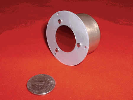
Sensor Physical Characteristics:
WEIGHT: less than 100 grams
POWER: less than 50 mwatts using a ±5 vdc. power supply
PRICE/SENSOR: $16,000- (in quantities of 2)
Disclaimer: satsearch is not responsible for any mistakes on this page, although we do our best to ensure correctness. Please report any mistakes to us.
Last updated: 2020-06-11
Earth Sensors / Horizon Scanners for Micro-Satellites
Export